1. Introduction
Installing a SCSI HD - Page 1
Source: Maxtor
- Introduction
The five steps to installing a SCSI hard drive are;
- Setting the jumper configuration
- Connect the Data cable
- Connect the Power cable
- Define drive parameters at the SCSI Host Adapter. (default or automatic
choices are best)
- Partitioning and formatting.
Before you begin, you must remove static electricity. This can be avoided by
simply touching the metal case of your PC. You must have the computer plugged-in
for this to be effective.
- Jumper Configuration
All SCSI devices inlcude 3 jumpers in order to define the drive's SCSI ID string.
Please refear to your SCSI hard disk manual for setting the proper jumper ID.
If case 2 devices have the same ID, during boot-up process, the system will
not detect them (and probably will not proceed). On a Quantum SCSI drive there
are two locations for drive options. Most Quantum SCSI drives have an option
connector at the front and back of the drive. Use only one jumper option connector
and be sure to orient the jumpers correctly.
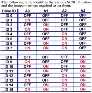
Note: ID 7 is normally used by the SCSI Host Adapter.
Each SCSI device on the bus must have a unique SCSI ID number. The drive can
be configured for SCSI ID numbers that range from 0 through 15. Set the SCSI
ID for the drive at the 12-pin Option connector or the 28-pin Secondary Option
connector. Jumper locations are shown. Refer to your system or SCSI Host Adapter
documentation for recommendations about assigning SCSI ID numbers for your specific
system.
2. Power Tips
Installing a SCSI HD - Page 2
Source: Maxtor
- SCSI Termination Power
To ensure that there is a sufficient level of power along the entire SCSI bus,
we recommend that all devices on the SCSI bus supply Termination Power (if they
are capable). SCSI devices are protected by a diode or similar semiconductor,
to prevent back flow of the terminator power when more than one device supplies
this power. Configure the drive to provide Termination Power by installing a
jumper across the appropriate connector on the Secondary Option Connector located
on the front of the drive. Most drives intended for File Servers have features
of minimal value in a PC configuration. For the most part, these minimal use
features are disabled by default. These options include Spin Delay, Force Narrow
mode, and others. They can typically be ignored. It is important to confirm
whether a function is enabled or disabled. That is, it needs a jumper in place,
or off, before proceeding further.
- Power Cable
Power cables must be connected correctly and securely. The System power supply
must be rated to accept today's 7,200 and 10,000 RPM drives. Spin up /down errors
may result. See your system manufacturer to confirm the power source is rated
for today's high speed drives. To insure proper connection the power cable connector
is keyed so that the connector can only fit onto the drive's four power pins
correctly. After you insure pin alignment, firmly push the cable into place.
3. Cables
Installing a SCSI HD - Page 3
Source: Maxtor
- Data Cable
 There
are many types of SCSI cables-internal and external. Usually the cable supplied
with the SCSI controller is adequate. If you're using both internal and external
cables, be sure all cable sets are from the same manufacturer. Mismatched cable
independence ratings causes signal reflections. If you are using a SCSI LVD
drive, 'twisted pair' cable sets and system level (cable attached) terminators
should be used. Poor quality cables result in excessive error correction. Refer
to your SCSI controller manufacturer or system manufacturer for details on choice
of SCSI cables and terminator. It is commonly said over 90% of SCSI errors can
be traced to inattention to SCSI cable and termination concerns.
There
are many types of SCSI cables-internal and external. Usually the cable supplied
with the SCSI controller is adequate. If you're using both internal and external
cables, be sure all cable sets are from the same manufacturer. Mismatched cable
independence ratings causes signal reflections. If you are using a SCSI LVD
drive, 'twisted pair' cable sets and system level (cable attached) terminators
should be used. Poor quality cables result in excessive error correction. Refer
to your SCSI controller manufacturer or system manufacturer for details on choice
of SCSI cables and terminator. It is commonly said over 90% of SCSI errors can
be traced to inattention to SCSI cable and termination concerns.
When properly connected both the power and data cables will present a snug secure
connection to the drive. When connecting the data cable you want to make sure
that Pin # 1 on the SCSI host adapter is connected to Pin # 1 on the drive.
Data cables have a stripped edge to help facilitate this configuration. Pin
# 1 on the SCSI host adapter should be well marked but if you cannot find it
you will need to reference your Motherboard manual or contact the SCSI host
adapter manufacture. Pin # 1 of the data cable interface on a Quantum SCSI hard
drive is always located next to the power connector. The red stripe on the data
cable should be faceing the red wire of the power connection when properly attached
to the drive.

Standard SCSI flat ribbon (Teflon) data cable
Ribbon data cable is commonly used internally, on SCSI Single Ended drives.
If you are installing only a single drive, place it at the end of the data cable.
Consult your SCSI Host Adapter documentation or system manufacture for details
on SCSI cable placement.

SCSI LVD (Low voltage differential) Twisted-pair cable.
Twisted pair data cables and system level (external) bus termination is required
for LVD drives running at SCSI Ultra2 or Ultra3 speeds. A twisted pair cable
set has greater immunity to signal (cross-talk) interference. System level termination
allows easy exchange of SCSI peripherals without regard to bus termination concerns.
When properly connected, both the power and data cables present a snug and
secure connection to the drive. SCSI data cables typically have a missing pin
to help identify correct orientation. (In some cases the connector is keyed),
but if you cannot locate it, you must reference your System manual or contact
the SCSI Host Adapter manufacturer for assistance.
 68 pin Twisted Pair Data Cable
 Active LVD Terminator
Once you have installed jumpers on the drive(s), and data and power cables connected,
turn on the PC (but leave the cover off). Listen to the hard drive to be sure
the disks are spinning.
4. Setting SCSI Adapter
Installing a SCSI HD - Page 4
Source: Maxtor
- Define the drive in the system's SCSI Host Adapter
A SCSI Host Adapter of recent build, with BIOS support for Logical Block Addressing
(LBA) generally can detect the full physical capacity of today's large capacity
hard drives (>8.4 GB). If you are unsure of your SCSI host adapter's ability
to detect the drive or its full capacity, consult your PC manufacturer or SCSI
host adapter documentation to determine if it supports of large capacity hard
disk drives. A BIOS or ASPI driver update may be needed.
There are many ways to configure your SCSI device(s) and host adapter setting
according to your needs. It is impossible to mention every variation. For the
purposes of this section, we'll focus on installation of a hard drive in a PC
compatible system with a DOS/ Windows 9x configuration. Your computer system
or host adapter vendor is the best resource for the latest product information
on device driver support, cable, and SCSI termination concerns.
 SCSI Host Adapter BIOS
5. Partition/Format
Installing a SCSI HD - Page 5
Source: Maxtor
- Partition and Format
The final step to preparing a drive for use is to partition and format it.
Partitioning the drive defines the storage area and prepares the drive to accept
data. Formatting sets up the File Allocation Table (FAT).
At this point you will need to decide what Operating System you will be installing.
For Win9x Operating Systems you will use fdisk.exe to partition the drive and
format.com to format. If you will be installing Win NT, partitioning and formatting
is part of the Operating System installation process. If you use fdisk.exe from
Win95 second edition, Win98, or Win2000 the "Large Drive" screen will be the
first page displayed.
 Large Drive Screen
Answering Yes will create a 32bit FAT (File Allocation Table). FAT 32 will support
partitions sizes up to two terra bytes. If you answer No, a 16bit FAT will be
created which allows for only two GB partition sizes. Once you answer Y or N
the next screen displayed is the fdisk main menu.
 Fdisk Main Menu Option Screen
- Menu Item #1 is used to create Pri DOS, Logical, and Extended partitions.
- Menu Item #2. is used to set a Pri DOS partition Active.
A partition must be set Active in order to make it bootable.
- Menu Item #3. is used to delete Pri DOS, Logical, Extended, and Non-DOS
partitions.
- Menu Item #4. is used to display partition information.
- Menu Item #5. is viewable only if you have two or more SCSI drives installed
in the system. It is used to toggle between the drives.
After you have created your partition it will need to be formatted. If the
drive you are installing is the C: drive you will need to boot from a floppy
that has a copy of fdisk.exe, so you can create the partition, and a copy of
format.com that you will use to format the partition. At the A: prompt you would
enter;
format C:/s (the /s copies the system files to the hard drive).
If you are installing a second, third, or forth drive you would, at the C:
prompt type format and the drive letter of the partition(s) you just created
followed by a colon.
For example if you just installed a second hard drive and made two partitions
on it you would type
format D: at the C: prompt.
When that partition is done formatting you would then type;
format E: (for the second partition)