1. Introduction
 DaTARIUS has a long and impressive history: it started as Koch in the 1980s, and the company was the second in Europe to replicate CDs. At that time, test equipment did not exist, so they built their own.
After developing the first quality control analyzer for the optical media industry, DaTARIUS has continued to set standards and design breakthrough solutions, all of which have led to success for many major replicators.
The DaTARIUS name was created in 2000, following the separation of Koch test equipment from the kdg media manufacturing group. Within three years, DaTARIUS acquired three major names in the inspection, testing and verification equipment market – CD Associates, the optical disc branch of Integral Vision, and the assets of aeco Ltd (formerly Aerosonic).
From the DaTARIUS web site.
---
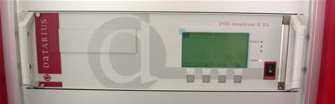
The DaTARIUS DVD Analyzer R 2x
The DaTARIUS DVD Analyzer R 2x is one of the cornerstones in DVD quality control equipment, and is truly unique in the industry. It allows checking of replicated DVDs with single and dual layer structure (DVD-5, DVD-9, DVD-10, DVD-14, DVD-18) and written DVD recordable, at 1X and 2X speed. It is based on the Pulstec Reference Pickup and Drive, developed in close co-operation with Pulstec and according to the standards of the DVD Forum.
In short, the device's features include:
- Analysis of pre-recorded DVDs, single and dual layer, and written DVD recordable
- Analysis of pre-recorded DVDs, single and dual layer, and written DVD recordable
- Double and single speed analysis
- Double-check function at reference speed
- Double-check function at reference speed
- Multi-dimensional calibration
- HF, jitter, mechanical and tracking parameters checked
- Radial tilt control, focus offset compensation and slicing level adjustment for jitter measurement
- Local defect detection/missing pits
- Error flag analysis (PI-errors, PI-fail, PO-fail)
- According to DVD Forum specification
- Double-Check function
- Control data simulation
- DVD-9 OTP sector number check

Following, is a brief explanation of the various parameters the DaTARIUS DVD Analyzer R 2x offers. The measuring parameters spread out over the next few pages, are divided into Analogue Signals, servo and tracking, time based, digital error and mechanical parameters.
2. Analogue Signals
With CD and DVD, the data structure is based on the time period or "T". On the High Frequency (HF) signal of the CD, we can find pits and lands whose lengths range from T3 to T11. It means that the shortest information element (T3) has a length three times the length of one period, where T has a length of 231 nanoseconds. In order to achieve a higher data rate, DVD uses "T" or a period of 38.2 ns. This equals an approximate data rate increase of six times that of the audio CD. The HF signal of DVD presents T3 to T11 pits and lands, but also T14.
The continuously measured signal, reported for every megabyte of data. It is equal to the highest possible reflection measured on a T14 land. Below you can see an illustration of the HF signal (eye-pattern I14H).

The I14H signal is related to:
- the dye layer thickness and absorption
- reflectivity and also thickness of the reflective layer
- the transmission of the substrate
- the optical laser power (usually automatically regulated and normalized within the pick-up unit).
Too low a value of reflectivity may result in problems with the read-out of the data. The signal is defined by several features related to the design of the whole DVD+R/-R discs. The primary cause of an actual value of I14H should always be looked for in the dye or recording material. One should consider the dye thickness, but in addition, the recording mechanism seen through the HF signals modulation values. The other reason may be simply the thickness of the reflective metal layer. This may be confirmed quickly by checking the transmission of light through the disc.
| |
Specification |
DaTARIUS |
| Limits DVD+R/-R DVD-5 |
Min |
0.45 |
0.45 |
| |
Max |
0.85 |
0.85 |
| Limits DVD-9 |
Min |
0.18 |
0.18 |
| |
Max |
0.30 |
0.30 |
| Measured |
From |
|
0 |
| |
To |
|
1 |
| Decimal places down |
|
3 |
Note that the signal I14H is equal to the signal R14H. The difference is that the R14H signal is measured only on given positions, defined in the program area (lead-in, lead-out, middle and data area).
-
I14Hrv - I14H Variation Within One Revolution
The signal reflects the I14H variation within one revolution of the disc.
I14Hrv = (I14H max - I14H min) / I14H max
The continuously measured value was introduced to verify the variations in the metallization layer along one revolution.
Effectively this parameter expresses a local variation of disc reflectivity. Being a continuously measured value it was introduced to verify the variations in the thickness of the dye layer and metal mirror layer along one revolution. It is related to the homogeneity of dye coating and/or reflective metal coating.
|
Specification |
DaTARIUS |
| Limits DVD+R/-R/-RW/ DVD-5/ DVD-9 |
Max |
0.15 |
0.15 |
|
|
|
|
| Limits DVD+RW |
Max |
0.25 |
|
| Measured |
From |
|
0 |
|
To |
|
1 |
| Decimal places down |
|
3 |
-
I14M - I14 Normalized Modulation
I14M = I14 / I14H (normalized I14)
The I14 amplitude is detected by measuring the level difference of the HF signal in the moment the laser beam passes a T14 land or T14 pit. Normalizing compensates influences from media (like variation of reflectivity) and /or the drive (different laser power). Due to normalization, the value becomes dimensionless. The property is also called I14 Modulation. For recordable media it is related to the recording mechanism within the disc.
The actual value of the I14M signal is linked directly with the mark recording, as as such with the dye recording properties itself, dye thickness in groove, and the groove dimension. In the lesser level it can be related to the reflective layer thickness, its thermal conductive properties and even the type and thickness of lacquer or bonding material.
|
Specification |
DaTARIUS |
| Limits DVD+R/-R/RW |
Min |
0.6 |
0.6 |
|
Max |
|
|
| Measured |
From |
|
0 |
|
To |
|
1 |
| Decimal places down |
|
2 |
-
I3M - I3 Normalized Modulation
Not directly mentioned in the specifications, but expressed through the parameter called resolution.
I3M = I3 / I14H
The continuously measured value reported for every megabyte of data represents the normalized I3 amplitude: in other words, it describes the signal coming from the shortest recorded spots.
Too low or too high a value of I3M is seen in the slicing level and signal asymmetry value. This signal is very sensitive to the length od space/land and length of spot preceding it. The effect is called inter symbol interference (ISI). The value is coupled with the overall disc design. In practice, should it require any correction, one should look at:
- The dye, its properties and thickness in the groove
-The groove depth and width
- The reflective layer metal layer (less critical)
No limits specified for I3M.
The Resolution signal is a relation of the amplitude of I3 and I14 (see previous graph).
RES = I3 / I14
In other words, this is the ratio of the HF modulation corresponding to I3 and I14 recorded spots.
A high resolution is preferred in order to make a clear distinction between I3 and I14 signals. A high resolution means well defined I3 marks. These marks are always the most sensitive to any changes in the media itself, in the recording strategy and even to the sequence of marks recorded directly before. Any causes lying behind a low value of resolution are similar to the behavior of other modulation types of signals described above. What should be emphasized is that the recording of I3 marks is one of the most difficult, and most sensitive to manufacturing process and recording method. A systematic low value of resolution is most probably caused be the deficiency of the dye and /or the process. The reason can be the dye itself, the groove design or the dye thickness or metal reflective layer thickness. The actual applies writing strategy can also influence recorded marks formulation, and particularly strongly, the shortest one, such as I3. However, its medium has its own optimized set of writing pulses which are implemented in the disc information, and possibly used by the recorder firmware. So any modification on this element would require a new master and eventually, consultation with the drive supplier.
|
Specification |
DaTARIUS |
| Limits DVD+R/-R/RW DVD-5 |
Min |
0.15 |
0.15 |
|
Max |
|
|
| Limits DVD-9 |
Min |
0.20 |
0.20 |
|
Max |
|
|
| Measured |
From |
|
0 |
|
To |
|
1 |
| Decimal places down |
|
2 |
The asymmetry signal (ASYd) reflects the relation of the position of I3-signal's mid-value to I14-signal's mid value.
ASYd = (I14H + I14L) - (I3H + I3J) / 2 * (I14H - I14L)
The signal is continuously measured and reported for every megabyte.
The importance of asymmetry lies in its value in determining the slicing level in the further signal processing chain. Subsequently, this leads to a determination of the signal values including deviation and Jitter as well as digital errors. This leads to the definition of the writing strategy. Each writing strategy (different for each writing speed) is encoded in the blank disc through pre-pits or wobble phase modulation (+R), or implemented in the recorder drive firmware. noticing high or low value of asymmetry can have several causes, such as:
- The drive is defective
- Media properties: dye, dye thickness, groove geometry, metal mirror layer, are out of particular media technology limits.
|
Specification |
DaTARIUS |
| Limits DVD+R/-R/RW/DVD-5 / DVD-9 |
Min |
-0.05 |
-0.05 |
| |
Max |
0.05 |
0.05 |
| Measured |
From |
|
-0.25 |
| |
To |
|
0.25 |
| Decimal places down |
|
1 |
TSC - Track Crossing Signal
This signal is evaluated in the 'open loop' mode, which happens while the DVD is spinning and the focused laser beam passes the track at right angles. The HF signal is fed through a low pass filter and the modulation of the signal is detected. The modulation results because the average reflection between the tracks is higher than on the track. This means that the modulation of the signal is a value for the cross-talk of adjacent tracks.
TCS is directly related to basics like dye layer thickness in groove against dye thickness on land, dye leveling, groove geometry and its molding quality. It does not depend on reflective metal layer thickness or bonding quality.
|
Specification |
DaTARIUS |
| Limits DVD+R/-R/RW DVD-5 |
Min |
0.10 |
0.10 |
| |
Max |
|
|
| Limits DVD-9 |
Min |
0.20 |
0.20 |
| |
Max |
|
|
| Measured |
From |
|
0 |
| |
To |
|
1 |
| Decimal places down |
|
3 |
3. Servo and Tracking Parameters
- DPDAmp - Differential Phase tracking Error Signal Amplitude
The differential phase tracking error signal amplitude is measured in the open loop mode. The serrated signal results from the phase signals of the quadrants of the diode, which are located diagonally to the track direction and after a special preparation of the signals.
For pre-recorded media, DPT returns information about the pit geometry in the radial direction. A high DPT value means that the radial flank of the pits have a steep slope. A low DPT value means that the radial flanks of the pits have a gentle slope.
To avoid tracking problems in consumer players, the DPT signal is specified to range from 0.5 to 1.1.
Flanks that are too steep or too gentle do not offer better tracking. There is an optimal slope for pits. therefore, to stay as close as possible to the optimum, DPDT has to stay between the specified limit.
For recordable media we cannot consider the slope of the pit, but we can consider how well the beginning of the recorded mark are defined. This depends on the decomposition properties of the dye used, design of the media and the applied writing strategy. The combination of these properties gives a pattern of electrical signal that corresponds to one given by a pit with a slope. However, we can talk about the optical equivalent rather than a physical limit.
|
Specification |
DaTARIUS |
| Limits DVD+R/-R/RW/ DVD-5 /DVD-9 |
Min |
0.5 |
0.5 |
|
Max |
1.10 |
1.10 |
| Measured |
From |
|
0 |
|
To |
|
1.25 |
| Decimal places down |
|
2 |
-
DPDAsy - Differential Phase tracking Error Signal Asymmetry
This value is a measure of the DPDamp signal position in relation to the zero level.
For typical pre-recorded media we can say that an asymmetry in the DPDamp signal means the radial flanks of the pits do not have the same slope.
For recordable media we can think in an analogous way to pre-recorded media. Yet in this case 'radial flanks' mean the deformation of the side walls of the groove during recording. We know that writing a mark does not only mean a decomposition of the dye and deformation of bottom of the groove, but also a deformation of the side walls of the groove. This side wall of the groove is apparent and depends on the type of dye.
Similarly, the prime slope of the groove can be responsible for the level of the side wall deformation during recording. This can be seen by testing media made with the same dye but using different groove geometry.
| |
Specification |
DaTARIUS |
| Limits DVD+R/-R/RW/ DVD-5 /DVD-9 |
Min |
-0.20 |
-0.20 |
| |
Max |
0.20 |
0.20 |
| Measured |
From |
|
-0.25 |
| |
To |
|
0,25 |
| Decimal places down |
|
1 |
-
TPP - Tangential Push -Pull
TPP is a continuously measured value reported every megabyte and is better known as the tangential push-pull signal. This signal reflects the difference of the diode pairs, which are located in the radial direction (front and back side of the detector).
Responsibility for TPP lies in the definition of the beginning and end of the recorded mark rather than in the form of the side walls of the groove. (recordable media). Again, the major factor ruling this parameter is the dye and the recording method used.
|
Specification |
DaTARIUS |
| Limits DVD+R/-R/RW/ DVD-5 /DVD-9 |
Min |
|
|
|
Max |
0.9 |
0.9 |
| Measured |
From |
|
0 |
|
To |
|
1 |
| Decimal places down |
|
2 |
The continuously measured value, reported for every megabyte, is measured according to the DVD specifications. This signal reports the deviations, which have a frequency between 1.1 and 10 KHz.
The centre of the pits on a track is not really on the same line. The PUH has to move (to the left or to the right) to centre itself and follow the pits. The radial movements from the nominal positions of the pick-up head are expressed in nanometers.
Peaks in the radial noise signal means that the PUH has to make an abnormal radial deviation, which can be caused by a black spot, a scratch, a bump, a dot etc. The signal is also related to the roughness of the side wall of the groove. For the recorded DVDR this is additionally enhanced through the recording process itself. Thus one may always expect a higher value of radial noise on the recorded media than on the corresponding blank one. Moreover, radial noise is a good indication of the quality of the stamper during the media manufacturing.
|
Specification |
DaTARIUS |
| Limits DVD+R/-R/RW/ DVD-5 / DVD-9 |
Min |
|
|
|
Max |
0.016 |
16 |
| Measured |
From |
|
0 |
|
To |
|
25 |
| Decimal places down |
|
0 |
| Unit |
μm |
nm |
The continuously measured value, reported for every megabyte, is measured according to the DVD specifications. This signal is comparable to RADIAL1 (radial noise), but reports only the deviations, which have a frequency of less than 1.1 KHz. This kind of deviation represents a long succession of pits whose position is abnormally far from the default position of the pick-up head.
RAD1 shows the longer deviations of the side walls of the groove. These types of defects are more likely to be caused during the mastering process rather than during the media manufacturing itself. One may expect to see in the signal, variations in the track pitch which can come from faulty mastering.
| |
Specification |
DaTARIUS |
| Limits DVD+R/-R/RW/ DVD-5 / DVD-9 |
Min |
-0.022 |
|
|
Max |
0.022 |
22 |
| Measured |
From |
|
50 |
|
To |
|
0.2 |
| Decimal places down |
|
0 |
| Unit |
μm |
nm |
Continuously measured, this signal reflects the axial/vertical deviation of the pick-up.
The distance between the PUH and the surface of the disc is variable. When the deviation is greater than the deviation specified/allowed, the spot is not optimally focused on the track and can result in read-out/tracking problems. The signal reports the deviations, which have a frequency below 10KHZ.
Axial deviations can be caused by bumps or dishing/skew.
|
Specification |
DaTARIUS |
| Limits DVD-5 / DVD-9 |
Min |
-0.23 |
|
| |
Max |
0.23 |
230 |
| Measured |
From |
|
0 |
| |
To |
|
500 |
| Decimal places down |
|
0 |
| Unit |
μm |
nm |
Mechanical parameters
The scaled, continuously measured value reflects the distance between adjacent physical track centerlines in the radial direction.
When the laser spot is on the track, the returned signal also affects information from the adjacent track. The phenomenon can disturb the correct read-out of the disc. Therefore, the space between the tracks should be large enough so that the laser spot highlights the information from one track and a minimum from the adjacent tracks.
|
Specification |
DaTARIUS |
| Limits DVD+R/-R/+RW/ DVD-5 /DVD-9 |
Min |
0.71 |
0.71 |
|
Max |
0.77 |
0.77 |
| DVD-RW |
Min |
0.73 |
|
|
Max |
0.75 |
|
| Measured |
From |
|
0.40 |
|
To |
|
1.65 |
| Decimal places down |
|
2 |
| Unit |
|
μm |
Scanning velocity corresponds to the speed at which the laser's pick-up head travels along the spiral track of the disc. This continuously scaled value is calculated by measuring the radius and the exact time for one revolution. The resulting value corresponds to the speed at which the laser's pick-up head travels along the spiral track of the disc.
The value of scanning velocity specified for both DVD-R and DVD+R discs is equal to 3.49 m/s /s, and corresponds to the nominal Channel bit rate 26, 15625 Mbits/s.
The electronics of a player can read-out data at different speeds, depending on their hardware specifications.
|
Specification |
DaTARIUS |
| Limits DVD+R/-R/RW/ DVD-5 |
Min |
3.46 |
3.46 |
| |
Max |
3.52 |
3.52 |
| DVD-9 |
Min |
3.81 |
|
| |
Max |
3.87 |
|
| Measured |
From |
|
3 |
| |
To |
|
4.25 |
| Decimal places down |
|
2 |
| Unit |
m/s |
m/s |
4. Time-based Parameters
Combined jitter relative to PLL clock. The PLL is a pulse with a period length equal to T or 38.2 ns, and is generated from a digitized data stream. The digitized data stream will be compared to this PLL clock. All present length effects in the data stream are used to form a histogram (JCH) from which the jitter value is being calculated. The standard deviations or jitter of the measured values are normalized to the PLL clock. The jitter generated by the variance from a DVD to the reference plane is compensated with the equivalent tilting from the pick-up optical axis.
JC is the standard deviation of the falling and rising edge of the digitized and equalized HF signals in respect to the PLL clock.
For pre-recorded media, a high jitter value means that pits and lands are shorter or longer than their specified length. If these variations are above a specific tolerance, read-out failures will be generated because of a wrong decision on the nature of a pit or land.
Jitter is also a rather complicated matter in recordable media. As with other signals, dye properties play a crucial role in the value of jitter of the written marks. In addition, the writing strategy and its implementation in the writer used can influence the Jitter as well. Moreover, phenomena related to the sequence of different recorded spots and lands (spaces) called inter-symbol interference, also influence the length of recorded marks.
The primary feature responsible for jitter in recordable media is the dye itself and its decomposition properties. The actual media jitter is a result of tedious optimization of dye application, and writing strategy formulation suitable for each speed.
|
Specification |
DaTARIUS |
| Limits DVD-R/-RW/ DVD-5 /DVD-9 |
Min |
|
|
|
Max |
0.08 |
0.08 |
| DVD+R/+RW |
Min |
|
|
|
Max |
0.09 |
0.09 |
| Measured |
From |
|
0 |
|
To |
|
25 |
| Decimal places down |
|
2 |
Digital Error Parameters
In order to make an error correction possible, redundant data has to be added to the user data. With DVD, the user data are organized to form a matrix. The width of the matrix is 172 columns and the length of each data sector is 12 lines (172 x 12). All together 16 data sectors are dedicated to this matrix, which results in a total of (12 x 16) = 192 lines.
With the assistance of a special algorithm, two sections of parity data are computed out of the original data and added to that original data. First of all, to each of the 172 columns, 16 bytes of PO parity data are generated, through which the matrix is enlarged from 192 to 208 lines. Again, of each of the 208 lines, 10 bytes PI parity data are generated. The matrix is now 182 columns wide.
This enables a player to correct at least five defective bytes in each line and at least eight defective bytes of each column. With the assistance of various alternating calculations over the lines and the columns it is possible to correct more defective bytes.
For the evaluation of the following error flags a summary of eight matrix or ECC blocks is used.
-
PI Sum 8 - Parity Inner Code Error
The parity inner code error is a continuously measured value, reported for every megabyte. This is the number of parity Rows, summed over 8 consecutive ECC Blocks, containing any bad bytes.
Such errors can be caused by all optical defects that interfere with the normal data read-out procedure (scratches, dots, black spots, bubbles, etc). Local defects can cause the data contents to deteriorate Others causes can be jitter problems, stamper defects or a bad HF signal.
The other causes for high error rate can be the recording layer itself. For example, the dye layer can contain particles, and causes coating defects which, if the medium is not rejected during manufacturing process, can show a high error rate. Similarly, too thin layer of metal mirror can result in a high value of digital errors.
|
Specification |
DaTARIUS |
| Limits DVD-R/+R/RW/ DVD-5 /DVD-9 |
Min |
|
|
|
Max |
280 |
280 |
| Measured |
From |
|
0 |
|
To |
|
500 |
| Decimal places down |
|
0 |
-
PIF - Parity Inner Code Fail
The PIF signal or parity inner code first level fail is a continuously measured value, reported for every megabyte. PIF is the number of rows within an ECC Block with too many bad bytes to allow error correction. All bytes in the row are marked bad.
Such errors can be caused by all optical defects that interfere with the normal data read-out procedure (scratches, dots, black spots, bubbles, etc). Local defects can cause the data contents to deteriorate Others causes can be jitter problems, stamper defects or a bad HF signal.
The signal is not specified in the DVD Book.
-
POF - Parity Outer Code Fail
Parity outer failure is a continuously measured value, reported for every megabyte. This occurs when the decoder is unable to correct all the data within an ECC Block after attempting one pass of PI Row correction and PO column correction.
The wording "first pass" is important because the decoder may be designed to make several passes of error correction. There is the possibility that bad bytes may be corrected in one of the subsequent passes. DVD and DVDR Tester decoders use one pass of error correction only.
Such errors may not be correctable and should be avoided on a DVD, since the data integrity is damaged.
Such errors can be caused by all optical defects that interfere with the normal data read-out procedure (scratches, dots, black spots, bubbles, etc). Local defects can cause the data contents to deteriorate Others causes can be jitter problems, stamper defects or a bad HF signal.
| |
Specification |
DaTARIUS |
| Limits DVD-R/+R/RW/ DVD-5 /DVD-9 |
Min |
|
|
|
Max |
0 |
0 |
| Measured |
From |
|
0 |
|
To |
|
250 |
| Decimal places down |
|
0 |
References:
DVD Specification for Read-Only-Disc Part 1 Physical Specification version 1.0
Standard ECMA 267 - 120mm DVD Read-Only Disc 2nd ed.
Datarius Group